From Connectors to Intelligent Cable Assemblies: The Evolution, Engineering and Future of Custom Connectivity
From crimp terminals and classic connector families to M8/M12, USB, RF/coaxial and AI-assisted engineering, the story of cable assembly is really the story of how machines learned to connect reliably.
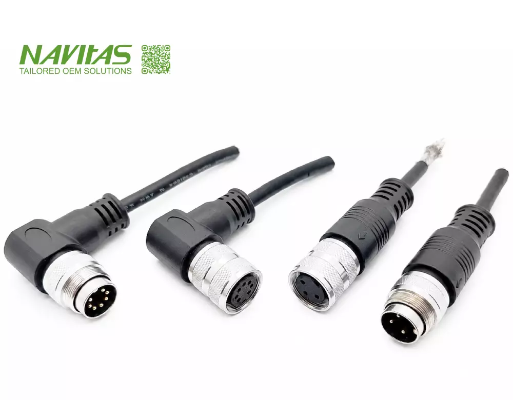
Table of Contents
- The History of Connectivity
- A Century of Connector Development
- D-Sub, USB, RJ45, M8/M12 and RF
- Good Cables Are Explained Well
- M8/M12 on the Factory Floor
- RF/Coaxial: Geometry Becomes Electrical
- Why Good Quotations Start With Questions
- Every Cable Has a Story
- Cable Engineering Is a Translation Business
- Engineering Review Before Manufacturing
- Taiwan's Changing Role
- AI's Two-Way Impact on Cable Assembly Engineering
- Future Connectivity Trends
- Engineering Knowledge Resources
- Connecting More Than Wires
- FAQ
1. The History of Connectivity Is the History of Electronics
A cable assembly may look simple: a connector on one end, another connector on the other, and wires in between. In reality, every reliable assembly carries decades of development in terminals, insulation, materials, shielding, tooling, crimping, molding and testing.
Early electronic systems relied heavily on soldered connections and relatively large interfaces. As production volumes increased, manufacturers needed connections that could be assembled faster, repeated more consistently and serviced more easily. Solderless terminals and crimp technology became fundamental building blocks of modern electronics.
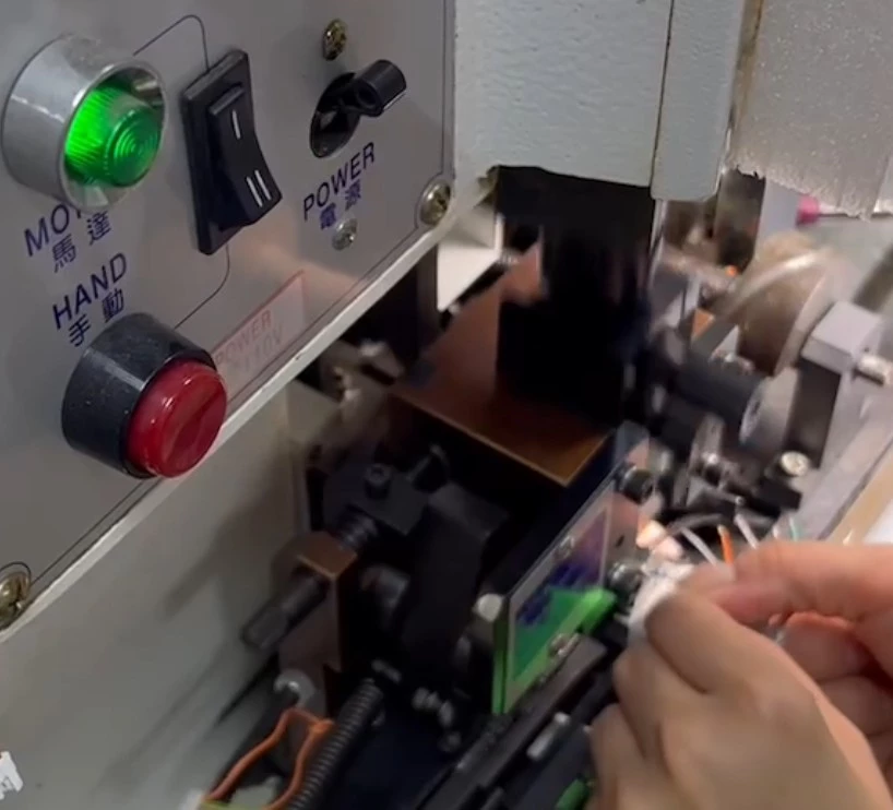
That change can still be seen on a modern production floor. The equipment is faster and more controlled, but the engineering principle remains recognizable: the conductor, terminal, tooling and process must be treated as one termination system.
2. A Century of Connector Development — Different Brands, Different Engineering Legacies
Molex, TE Connectivity / AMP, JST, JAE, Hirose, Samtec, CONEC, Amphenol and Phoenix Contact each developed expertise around different engineering problems: solderless termination, miniaturization, aerospace reliability, industrial automation, high-speed interconnects and rugged environmental connectivity.
Swipe horizontally to view the full brand history table →
| Brand | Historical Context | Engineering Relevance to Cable Assemblies |
|---|---|---|
| Molex | Molex traces its origins to the 1930s and evolved alongside radio, computing, automotive, telecommunications and connected electronics. | Wire-to-board, wire-to-wire, power, signal and compact interconnect systems commonly appear in custom harness projects. |
| TE Connectivity / AMP / Tyco | AMP's story began in 1941, when Uncas A. Whitaker developed a faster solderless electrical connection approach. AMP later became part of Tyco, and TE Connectivity emerged as a focused connectivity company. | Crimp termination, terminals, industrial connectors, transportation and harsh-environment interconnect systems. |
| JST | JST began with solderless terminal technology in Japan and later expanded into compact crimp connector systems used across electronics and industrial applications. | Compact wire-to-board and wire-to-wire systems where terminal selection, strip length and crimp control become increasingly important. |
| JAE | JAE grew from Japan's aviation-electronics environment into high-reliability and high-density connector technologies. | Aerospace heritage, compact interfaces and precision interconnect requirements. |
| Hirose | Hirose developed from early connector manufacturing into compact, RF, board-level and precision interconnect technologies. | Miniaturization increases sensitivity to strip length, terminal position, connector handling and assembly precision. |
| Samtec | Samtec's development reflects the industry's move toward high-speed, micro/rugged and advanced interconnect systems. | At higher data rates, cable assembly becomes part of signal-integrity engineering rather than simple pin-to-pin wiring. |
| CONEC | CONEC's product line grew out of D-Sub and circular connector technologies, later extending into overmolded and sealed industrial systems. | Industrial sealing, overmolding, ruggedization and application-specific connector systems. |
| Amphenol | Amphenol grew from early radio interconnection into broad RF, circular, industrial, sensor and antenna technologies. | RF/coaxial, circular, industrial, transportation and mixed power/signal systems. |
| Phoenix Contact | Phoenix Contact developed from electrical connection technology into broad industrial electrification, networking and automation solutions. | Industrial control, terminal technologies, field connectivity, automation and machine-level interconnection. |

For custom cable assembly engineering, the brand is therefore a starting point — not the complete answer.
3. Standard Interface Evolution: D-Sub, USB, RJ45, M8/M12 and RF
Brand-specific connector families tell one side of the story. Standardized interfaces show how the machines around them changed.
Swipe horizontally to view the full interface table →
| Interface | Why It Became Important | Engineering Focus Today |
|---|---|---|
| D-Sub | Computing, communications, test and industrial equipment | Mechanical retention, shielding, screw locking, overmolding and long-term serviceability |
| USB / USB Type-C | Standardized peripheral, data and power connectivity; USB4 Version 2.0 defines up to 80 Gbps bidirectional operation, with an optional asymmetric configuration of up to 120 Gbps in one direction and 40 Gbps in the other. | Differential pairs, shielding, power delivery, cable construction, connector PCB transition and compliance requirements |
| RJ45 | Ethernet networking from office systems into industrial equipment | Cable category, shielding, locking, oil resistance, flexing and industrial environmental protection |
| M8 / M12 | Sensors, actuators, industrial networking and automation | Coding, pin count, sealing system, vibration, overmolding, mating condition and installation environment |
| RF / Coaxial | Radio, antenna, instrumentation and communications | Impedance, insertion loss, return loss, shielding, frequency range and connector transition |
A standardized interface does not eliminate engineering. It creates a common framework, while the complete cable assembly still has to fit the actual electrical, mechanical and environmental application.
4. Engineering Guidance: Good Cables Are “Explained Well” Before They Are Built
In custom manufacturing, many expensive problems begin with a sentence that sounds harmless:
If you have ever received a cable sample with no drawing and no pinout, you already know how quickly a “simple replacement” can become an engineering project.
A physical sample can show dimensions and connector style, but it may not explain conductor material, plating, internal shielding, approved equivalent components, environmental exposure, required flex life, mating cycles or what the cable is actually carrying.
A good engineering discussion turns an incomplete request into a manufacturable specification. That means clarifying not only what the cable looks like, but also what it must survive and what it must electrically accomplish.
Electrical
Current, voltage, signal type, impedance, data rate, grounding, shielding and pin assignment.
Mechanical
Length tolerance, routing, bend radius, strain relief, movement, connector orientation and pull-force criteria.
Environmental
Temperature, water, oil, chemicals, UV exposure, vibration, outdoor use and required IP performance.
These three dimensions are what turn a sample into a specification.
5. M8 and M12: When Connectivity Moved Onto the Factory Floor
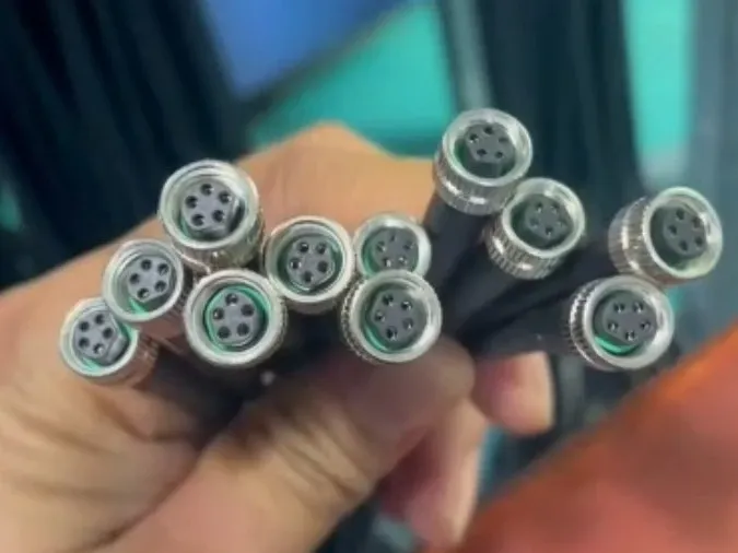
M8 and M12 connectors have become widely used circular interfaces for industrial sensors, actuators, automation equipment and industrial networking. Their value comes from compact form factors, standardized mechanical interfaces and application-specific coding — but the connector alone does not define the performance of the completed cable assembly.
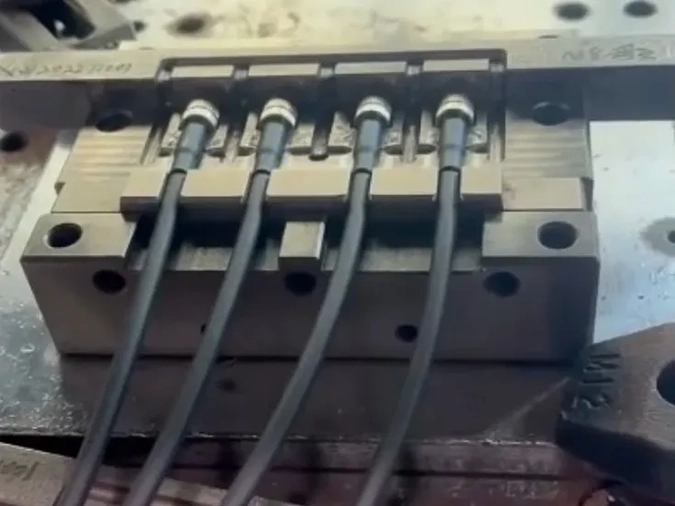
An IP-rated connector does not automatically make the complete cable assembly waterproof. Performance depends on the complete mated system: connector design, seals, cable jacket, overmold geometry, strain relief, assembly process, mating condition and the installation environment.
Continue with our M8/M12 Cable Assembly Knowledge Guide, or review our custom cable assembly manufacturing capabilities.
6. RF and Coaxial Cable Assemblies: When Geometry Becomes Electrical
RF/coaxial assemblies show particularly clearly why a cable cannot always be treated as a simple conductor. At higher frequencies, physical geometry becomes part of electrical behavior. Cable type, impedance, connector interface, shielding and assembly workmanship influence system performance.
A cable that passes continuity testing may still fail in the real application because continuity does not validate impedance, insertion loss, return loss or shielding performance.
An impedance mismatch is typically reflected in return loss and signal degradation, not in a simple continuity failure.
Explore NAVITAS RF & Coaxial Cable Assembly capabilities and our EMI shielding engineering guide.
7. Why a Good Cable Assembly Quotation Starts With Questions
A request such as “Please quote a one-meter M12 cable” is not yet a complete manufacturing specification. Responsible quotation requires enough information to price what will actually be built.
You do not need every answer on day one — but the more clearly you describe the application, the fewer assumptions have to be built into the quotation.
Swipe horizontally to view the full RFQ checklist →
| RFQ Item | What Should Be Confirmed | Why It Matters |
|---|---|---|
| Connector | Brand, series, part number, gender, pin count, pitch, orientation | Prevents mating and sourcing errors |
| Wire / Cable | AWG, UL style, conductor, insulation, color, jacket | Affects current, voltage, flexibility and environment |
| Length | Overall length, branch lengths and tolerances | Controls fit and assembly repeatability |
| Pinout | Pin-to-pin wiring, polarity, twisted pairs, drain/ground | Defines electrical function |
| Environment | Temperature, vibration, water, oil, UV, chemicals, flexing | Drives material and mechanical choices |
| Performance | Current, voltage, signal type, speed, impedance, EMI/IP needs | Prevents technically incompatible builds |
| Production | Quantity, prototype needs, equivalent parts, test plan | Affects cost, tooling, sourcing and lead time |
Equivalent parts should not be judged only by appearance or pitch. A substitute may fit physically but differ in terminal system, contact plating, rated current, housing material, operating temperature, locking method, tooling compatibility or mating performance.
A low quotation created from incomplete information may simply be a quotation containing more assumptions.
8. Problem-Solving: Every Cable Has a Story
When a cable fails in the field, the visible symptom is often not the real cause. A connector can be perfectly suitable, yet the completed assembly can still develop intermittent contact, water ingress, conductor fatigue or EMI problems.
If a cable has already failed in your equipment, replacing the visible connector may be the easiest action — but it is not necessarily the right diagnosis.
For example, reduced enclosure clearance can force a cable below its recommended bend radius. A jacket selected for static installation may be used in repetitive motion. A seal may be correct while the cable-to-overmold transition becomes the actual ingress path. A conductor may pass a continuity check but still be marginal for current, voltage drop or thermal conditions.
Effective problem-solving requires separating the symptom from the mechanism that created it.
9. Communication: Cable Engineering Is a Translation Business
A customer may send a drawing, photograph, old sample, BOM, connector part number, rough sketch or only an application description. Those sources can disagree with each other.
A drawing may specify AWG28 while the required current suggests a larger conductor. A photo may show shielding that does not appear in the BOM. A connector may physically fit but have an unsuitable current rating. An IP requirement may be stated without defining the mating condition or the actual exposure.
This translation work matters because factories cannot manufacture intent. They manufacture specifications. Clear communication is therefore not separate from engineering — it is part of engineering.
10. Engineering Review Before Manufacturing
The traditional model is simple: drawing → quotation → manufacturing → inspection → delivery. For engineering-sensitive custom cable assemblies, NAVITAS adds review earlier in the process so preventable risks can be discussed before tooling, samples or production.
Engineering collaboration is not one-way communication:
A practical pre-production review may include connector compatibility, conductor size, current and voltage, pin assignment, cable jacket, bend radius, strain relief, crimping, shielding, waterproofing, overmolding, operating environment, movement, terminal pull-force criteria, mating-cycle requirements, testing and manufacturability.

It is to identify expensive problems while they are still inexpensive to change.
11. Taiwan's Role: From Build-to-Print to Engineering Collaboration
Taiwan has long played an important role in the global electronics supply chain through manufacturing knowledge, component sourcing, tooling, flexible production and coordination across specialized suppliers.
But competing only on manufacturing cost is becoming less sustainable. A higher-value role is to move from Build-to-Print toward Build-to-Requirement and ultimately Engineering Collaboration.
Global OEM teams may understand their systems extremely well but may not specialize in every detail of crimp terminals, cable jackets, overmolding, shield termination or connector sourcing. A capable Taiwan supplier can bridge the gap between system requirements and a repeatable cable assembly process.
To: “We understand what you are trying to build, can identify manufacturing risks, and can help turn the requirement into a repeatable cable assembly.”
12. AI's Two-Way Impact on Cable Assembly Engineering
Artificial intelligence is beginning to influence both sides of the custom cable assembly industry. Engineers and purchasing teams can use AI to compare specifications, summarize datasheets, prepare preliminary BOMs and RFQs, and identify missing information. Manufacturers can use AI to extract drawing data, compare revisions, retrieve similar historical projects and flag possible conflicts for review.
Computer vision may also assist inspection by comparing finished assemblies with approved drawings for connector orientation, branch positions, labels or visible dimensions. But AI does not remove the need for validated specifications, testing and accountable engineering decisions.
13. Where Custom Cable Assemblies Are Going Next
Higher Data Rates
Machine vision, industrial Ethernet, AI computing and advanced sensors increase signal-integrity requirements.
Higher Power Density
Robotics, EV subsystems and distributed equipment require compact connections carrying more power.
Smaller Interfaces
Higher circuit density increases the importance of terminal, strip-length and crimp-process control.
Harsh Environments
Automation, outdoor equipment and transportation require better sealing, chemical resistance and durability.
Hybrid Connectivity
Power, signal, Ethernet and RF technologies increasingly coexist within the same machine.
Smarter Manufacturing
AI-assisted inspection, digital work instructions, automated testing and traceability will become more common.
As systems become more complicated, mistakes become more expensive. The economic value of preventing an error before tooling or mass production will continue to increase.
14. Continue With NAVITAS Engineering Knowledge
This article is a hub-style overview. Readers who need deeper technical information can continue into focused engineering resources.
15. Connecting More Than Wires
Most people never notice a good cable assembly. That is exactly how it should be. It sits inside a robot, industrial controller, medical device, machine vision system or communication product and quietly performs its job.
No one celebrates the strain relief that did not crack, the shielding that prevented interference, the crimp that remained stable, or the overmold that kept moisture out. Reliability is often invisible — but creating that invisibility requires engineering.
Connector manufacturers created essential building blocks. Standard interfaces expanded how equipment exchanges power, signals and data. Taiwan helped turn many of these technologies into manufacturable products for global industries. AI is now adding another layer by connecting drawings, specifications, historical data, inspection and engineering knowledge.
At NAVITAS, manufacturing should not begin only with the question, “Can we make this?” It should also ask, “Is this the right way to make it?”
16. FAQ: Custom Cable Assembly Engineering
What information is needed before quoting a custom cable assembly?
A useful RFQ normally includes connector manufacturer and part number, pin count, wire or cable specification, AWG, cable length and tolerance, pinout, shielding or environmental-protection requirements, application environment, quantity, testing requirements, and whether equivalent components are acceptable.
What is the difference between a cable assembly and a wire harness?
The terms overlap, but a cable assembly often refers to one or more insulated cables or conductors terminated with connectors and may include shielding, overmolding or environmental protection. A wire harness usually emphasizes organized routing and bundling of multiple wires or branches inside equipment. In practice, the exact construction and application matter more than the label.
Does an M12 connector automatically make a cable assembly waterproof?
No. Environmental performance depends on the complete mated system, including connector design, seals, cable jacket, overmold, strain relief, assembly process, mating condition and installation environment.
Why can a cable pass continuity testing but still fail in the application?
Continuity confirms an electrical path but does not prove signal integrity, shielding effectiveness, impedance control, flex life, sealing, strain relief, temperature capability or connector suitability.
Can an equivalent connector be used in a custom cable assembly?
Sometimes, but physical fit alone is not enough. The terminal system, current rating, contact plating, housing material, temperature range, locking design, tooling and mating compatibility should be reviewed before an equivalent part is approved.
How can AI support cable assembly engineering?
AI can help extract drawing data, compare BOMs and revisions, identify missing RFQ information, retrieve similar projects and flag possible risks. AI does not replace engineering validation: final decisions should still rely on verified source data, the actual application, testing requirements and human approval.
What is Engineering Review Before Manufacturing?
It is a pre-production review of connector compatibility, wire gauge, pinout, shielding, environmental protection, overmolding, strain relief, testing and manufacturability so preventable problems can be identified before tooling or production.
About NAVITAS
NAVITAS / Green Solar Tech. Co., Ltd. provides custom cable assembly and wire harness manufacturing support from Taiwan for industrial automation, robotics, medical equipment, EV-related systems, communication equipment and engineering-driven OEM projects.
Custom Cable Assembly Capabilities | Turnkey Cable Assembly Services | Technical Blog
Official References
Historical and interface statements in this article were cross-checked against official manufacturer or standards-organization sources.
Trademark notice: Molex, TE Connectivity, AMP, Tyco, JST, JAE, Samtec, CONEC, Hirose, Amphenol, Phoenix Contact, USB and other brand or product names mentioned in this article are trademarks or registered trademarks of their respective owners. NAVITAS / Green Solar Tech. Co., Ltd. is an independent custom cable assembly manufacturer. References to third-party brands are for identification and technical-information purposes only and do not imply authorization, sponsorship, endorsement, distributorship or affiliation.